Vacuum Gas Quenching Furnace
- Max Temp:1350℃/2200℃
- Atmosphere Types:Vacuum / N₂ / Ar
- Quenching Method:Gas quenching / Oil quenching
- Application:Tool steel, Die steel, Stainless steel, High-speed steel, Cemented carbide
-

Customized Vacuum Solutions
-

High Thermal Efficiency
-

Ultra-Clean Vacuum Environment
-

Stable & Repeatable Results
-

Industry-Grade Safety Design
Introduction
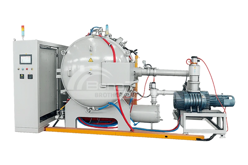
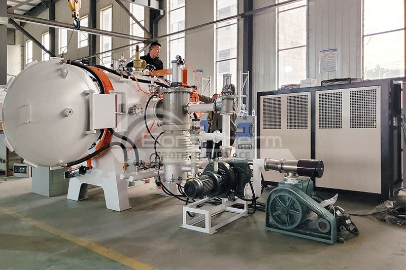
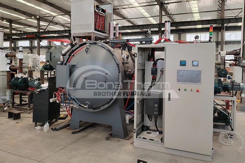
The vacuum gas quenching furnace is primarily used for vacuum bright quenching of tool steel, die steel, elastic alloys, stainless steel, and 3D-printed additive components. It is also suitable for sintering, brazing, and other heat treatment processes. The system typically consists of a pressure-rated furnace body, heating chamber, vacuum system, electrical control system, gas quenching system, water cooling system, pneumatic system, and external loading cart.
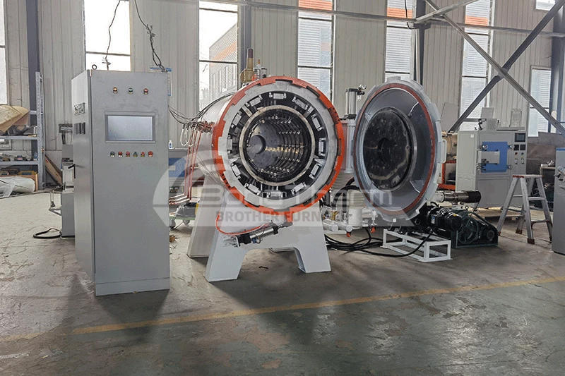
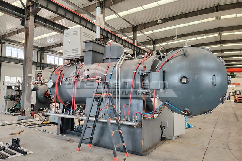
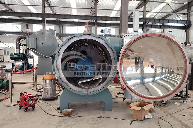
Vacuum Quenching Furnace in Production
 |  |  |
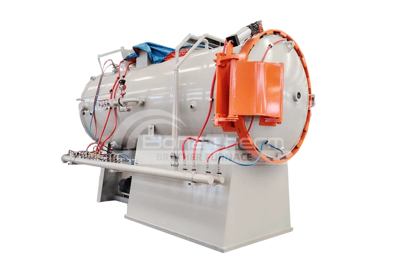
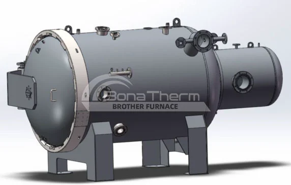
Furnace Body Structure
The Brother Furnace Vacuum Gas Quenching Furnace consists of the main vacuum furnace body, vacuum system, water cooling system, pneumatic system, gas backfilling system, electrical control system, and external loading/unloading cart.
1. Furnace Structure
- The furnace body and door are of a double-layer water-cooled design. The inner wall is made of pressure vessel-grade steel, and the outer wall is fabricated from Q235 carbon steel.
- Multiple interfaces are provided, including ports for evacuation, electrodes, thermocouples, gas inlet, pressure measurement, safety valve, and auxiliary functions.
- The door seal adopts a dual-direction locking ring design to ensure tight sealing under both vacuum and positive pressure conditions.
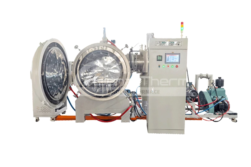
2. Heating System
- The heating chamber is a cylindrical structure, equipped with molybdenum strip heating elements and multi-layer metallic insulation shields.
- The heating elements are made of high-temperature Mo-La alloy, modular in design, uniformly distributed, offering excellent temperature uniformity and easy replacement.
- The furnace features a high-strength load platform that can withstand up to 100 kg at 1200 °C without deformation.
- Ceramic insulators are made from 99% Al₂O₃, ensuring excellent high-temperature insulation.
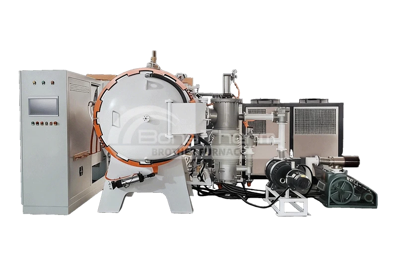
3. Rapid Cooling System
- Equipped with a high-power, water-cooled fan motor and an efficient heat exchanger.
- Inert gases such as nitrogen or argon are used as cooling media, with pressure up to 10 bar.
- Gas flow is evenly distributed into the furnace chamber through nozzles and guide plates to ensure uniform quenching.
- The fan speed is adjustable to meet different materials and process requirements.
4. Vacuum System
- The system comprises a mechanical pump and a Roots pump, achieving a final vacuum of up to 4.0×10⁻¹ Pa.
- Vacuum is monitored in real time using a digital resistance vacuum gauge, with fully automated sequence control.
- Features include safety valves, flexible metal hoses, and leak detection ports for improved safety and ease of maintenance.
5. Backfilling Gas System
- Inert gas backfilling is managed through fast and fine-flow systems.
- The fast-fill system supports rapid cooling, while the fine-fill system maintains pressure stability and reduces material evaporation.
- Pressure is automatically controlled via sensors, with overpressure relief valves ensuring safe operation.
6. Control System
- The system utilizes a Siemens PLC and a touchscreen HMI, supporting both automatic and manual operations.
- High-precision temperature control with multi-segment programmable heating curves and data recording.
- Built-in interlock protections against over-temperature, power failure, low water pressure, and other faults ensure safe operation.
7. Pneumatic System
- Includes air source processing units and multiple solenoid valves for controlling vacuum valves, gas valves, etc.
- Equipped with low-pressure alarms to ensure stable operation of the pneumatic components.
8. Water Cooling System
- A closed-loop water cooling system is used to cool the furnace body, vacuum pumps, electrodes, fan motor, and heat exchanger.
- Features include water pressure sensors, flow detectors, and alarm systems to ensure stable and reliable cooling performance.
- Independent valves for each cooling point allow for precise flow regulation.
Technical Parameters
Model | Chamber Size (W*H*D)mm | Max Temp(℃) | Heating Element | Capacity (kg) | Temp Uniformity(℃) | Power (kW) | Ultimate Vacuum(Pa) |
|---|---|---|---|---|---|---|---|
BR-QCL-334G | 300*300*450 | 1350 | Graphite | 100 | ±5 | 50 | 7x10⁻¹ |
BR-QCL-446G | 400*400*600 | 1350 | Graphite | 200 | ±5 | 80 | 7x10⁻¹ |
BR-QCL-557G | 500*500*700 | 1350 | Graphite | 300 | ±5 | 120 | 7x10⁻¹ |
BR-QCL-669G | 600*600*900 | 1350 | Graphite | 500 | ±5 | 150 | 7x10⁻¹ |
BR-QCL-8812G | 800*800*1200 | 1350 | Graphite | 900 | ±5 | 260 | 7x10⁻¹ |
Model | Chamber Size (W*H*D)mm | Max Temp(℃) | Heating Element | Capacity (kg) | Temp Uniformity(℃) | Power (kW) | Ultimate Vacuum(Pa) |
|---|---|---|---|---|---|---|---|
BR-QCL-334M | 300*300*450 | 1350 | Molybdenum | 100 | ±5 | 50 | 7x10⁻¹ |
BR-QCL-446M | 400*400*600 | 1350 | Molybdenum | 200 | ±5 | 80 | 7x10⁻¹ |
BR-QCL-557M | 500*500*700 | 1350 | Molybdenum | 300 | ±5 | 120 | 7x10⁻¹ |
BR-QCL-669M | 600*600*900 | 1350 | Molybdenum | 500 | ±5 | 150 | 7x10⁻¹ |
BR-QCL-8812M | 800*800*1200 | 1350 | Molybdenum | 900 | ±5 | 260 | 7x10⁻¹ |
Key Features and Advantages
- Graphite Heating Chamber: Constructed from graphite heating elements, soft graphite felt, and rigid graphite felt. Maximum operating temperature up to 1350°C.
- Multi-Row Graphite Nozzles: Uniformly distributed around the inner wall of the insulation layer in the heating chamber. During quenching, gas is evenly sprayed from the nozzles to achieve consistent cooling across the workpiece.
- Worktable Design: Composed of graphite columns, graphite base, and Al₂O₃ ceramic spacers to prevent sticking between the workpiece tray and the furnace bed at high temperatures.
- Optional Molybdenum Heating Structure: A high-temperature heating zone utilizing molybdenum strips and multilayer molybdenum foil heat shields. This design is non-volatile, impurity-free, and does not contaminate the workpieces.
- Efficient Gas Cooling System: Located at the rear of the furnace, comprising a high-pressure impeller fan, multi-stage copper heat exchanger, and airflow guide ducts.
- During gas quenching, high-purity nitrogen or argon is introduced and circulated by the impeller fan through the heat exchanger and duct system, then uniformly sprayed through graphite nozzles for forced, even cooling of the workpiece.
- Adjustable Gas Pressure: Quenching pressure can be set between 1 and 10 bar.
- High Cooling Efficiency: The furnace can cool from 1150°C to 250°C in less than 7 minutes under no-load conditions (cooling water temperature < 35°C).
Typical Applications
- Cutting Tools & Dies (e.g., drill bits, injection molds)
- Aerospace Components (e.g., turbine blades, rocket parts)
- Medical Devices (e.g., surgical tools, artificial joints)
- Automotive Parts (e.g., gears, bearings)